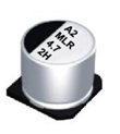
what isSMD aluminum electrolytic capacitor
For chip aluminum electrolytic capacitors , the material used for the cathode is electrolyte. This is the most widely used capacitor we have seen.
Its characteristics: first, the chip capacitor and the bottom plate are soldered with tin, and the bottom of the capacitor and the bottom plate are tightly attached, without any gaps at all; second, there are no solder joints on the back of the circuit board, so there is no possibility of causing a short circuit. . On the other hand, chip capacitors are higher than plug-in capacitors in terms of components and production process costs.

Whether there is a rubber base is the main basis for distinguishing SMT patch and direct plug packaging.
How to judge the positive and negative electrodes of chip aluminum electrolytic capacitors
The difference between the positive and negative poles of the chip aluminum electrolytic capacitor and the black block with the mark on the measuring capacitor is the negative pole. There are two semicircles on the PCB at the position of the capacitor, and the pin corresponding to the colored semicircle is the negative electrode. The length of the pins can also be used to distinguish the positive and negative poles. The long pin is positive and the short pin is negative.
When we don't know the positive and negative poles of the capacitor, we can use a multimeter to measure it. The medium between the north and south poles of the capacitor is not an absolute insulator, and its resistance is not infinite, but a limited value, generally above 1000 megohms. The resistance between the north and south poles of a capacitor is called insulation resistance or leakage resistance. As long as the positive terminal of the electrolytic capacitor is connected to the positive power supply (black test lead when the resistor is deflected) and the negative terminal is connected to the negative power supply (red test lead when the resistor is deflected), the leakage current of the electrolytic capacitor will be small (the leakage resistance is large). On the contrary, the leakage current of the electrolytic capacitor increases (the leakage resistance decreases). In this way, we first assume that a certain pole is a "+" pole, and the multimeter selects the R*100 or R*1K block, and then connects the assumed "+" pole to the black test lead of the multimeter, and the other electrode is connected to the red test lead of the multimeter. Note down the scale at which the needle stops (the resistance value is higher on the left side of the meter). For a digital multimeter, the reading can be read directly. Then discharge the capacitor (touch the two leads), then reverse the two test leads and measure from the beginning. In the two measurements, when the needle last stayed on the left (or had a high resistance), the black test lead was connected to the positive electrode of the electrolytic capacitor.


