Important things to know:
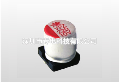
1.Solid capacitor polarity
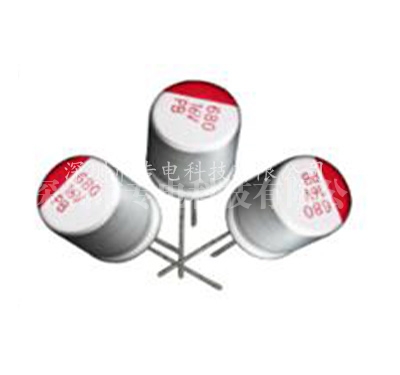
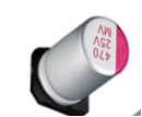
Solid aluminum capacitors have positive and negative poles. Do not connect solid aluminum capacitors reversely. Reverse connection of solid aluminum capacitors may cause a sharp increase in leakage current or a decrease in service life.
2. Circuits that are prohibited from use: Even if customers install solid aluminum capacitors in strict accordance with the welding conditions given by us, the leakage current of solid aluminum capacitors may increase, or even increase significantly. High temperature no-load test, high temperature and high humidity load test, sudden temperature change test, etc. may lead to an increase in leakage current. Therefore, please do not use solid aluminum capacitors in circuits that are sensitive to leakage current. For example:
a) High impedance circuit;
b) Coupling circuit;
c) Time constant circuit.
3. Solid capacitor operating voltage
a) The sum of DC voltage and ripple peak voltage shall not exceed the rated operating voltage;
b) When the DC voltage is relatively low, the reverse ripple peak voltage cannot exceed 10% of the rated operating voltage;
c) For products above 25V, when the ambient temperature exceeds 85°C, please use solid aluminum capacitors to reduce the voltage. For every 10°C increase in temperature, please reduce the voltage applied to the product by 10%.
4. Please select the appropriate solid capacitor according to the capacitance characteristics specified in the standard book.
a) Do not use it with overvoltage. Even a short-term overvoltage may cause a short circuit of the solid capacitor;
b) The ambient temperature used must be within the range specified in the standard book;
c) Do not apply more than the specified ripple current value to the solid capacitor. Excessive ripple current will cause excessive internal heating of the capacitor, which may lead to premature product failure or even short circuit.
5. Instantaneous charge and discharge: Instantaneous charge and discharge may cause a short circuit in the solid capacitor or an increase in leakage current. Therefore, please design a protection circuit under the following circumstances:
a) The impulse current is greater than 10A;
b) The impulse current is greater than 10 times the allowed ripple current value. In addition, when testing the product leakage current, please set a 1KΩ protection resistor.
6) Failure mode and life
Failure mode:
a) Occasional failure: Mainly caused by short circuit of the circuit. When the current in the short circuit circuit exceeds 1A, the internal temperature of the capacitor will rise, the internal pressure will increase, the sealing rubber may bulge or even open, and the capacitor will release harmful gases. Please leave this situation at this time;
b) Lifetime failure: During long-term use, the characteristics of solid capacitors will attenuate, such as capacity decrease, ESR increase, etc. When the use time exceeds the rated life, the characteristics of the capacitor deteriorate and can lead to electrolyte insulation. This is an open circuit failure mode.
Special reminder
1. Leakage current:
Welding heat and mechanical stress from transportation can cause the current of the capacitor to increase. However, applying a DC voltage that does not exceed the rated operating voltage to the product will gradually reduce the leakage current. As long as the rated operating voltage and upper operating temperature do not exceed Under the premise, the higher the applied voltage and the higher the ambient temperature, the faster the leakage current decreases.
2. Capacitor insulation:
The insulating coating or insulating hose layer outside the capacitor is not absolutely insulated. In addition, the aluminum shell and the negative lead are not insulated. When installing, be sure to completely isolate the aluminum shell, positive and negative guide pins, and PC board printing.
3. Solid capacitor operating environment requirements:
Please do not use solid capacitors in the following environments:
a) Places where water, salt water, and oil can drip directly, and circuit boards that are prone to shrinkage;
b) Occasions where harmful gases (H2S, sulfuric acid, ammonia, hydrochloric acid, etc.) accumulate:
c) Situations exposed to ultraviolet rays, radioactive rays, ozone and other radiation.
4. PCB board design
a) Do not install solid capacitors around or on heat source components;
b) The diameter and distance of the device holes on the PCB should match the diameter and pitch of the capacitor lead pins.
5. Parallel circuit: When a solid capacitor is connected in parallel with another (liquid) capacitor, because the solid capacitor has a much lower ESR value, there may be a large ripple current applied to the solid capacitor. In this case, Be sure to select capacitor standards carefully.
6. The electrical performance of solid capacitors will be affected by frequency fluctuations, and this factor should be considered when designing the circuit.Chip capacitor
7. When installing solid aluminum capacitors on a double-sided PCB, please do not install solid aluminum capacitors in the holes connecting the front and rear PCB boards.


